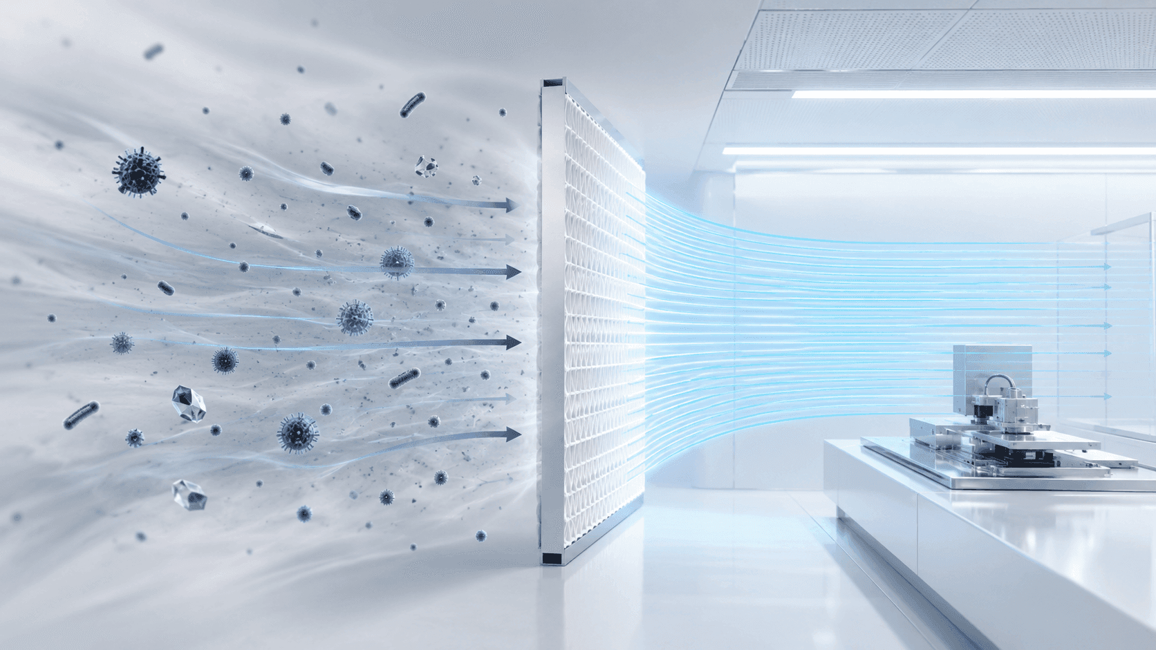
Air filtration is a fundamental part of contamination control in cleanrooms and clean zones. HEPA and ULPA filters are widely used to remove airborne particles, but they differ in filtration performance, airflow resistance and suitable applications.
Developments in nanofiber filtration are also creating new possibilities for environments that require ultra-high particle removal without accepting the airflow penalty commonly associated with more restrictive filter media. FERENA technology is one such approach.
This article explains how HEPA, ULPA and FERENA filtration differ, how high-efficiency filters capture particles and why filter efficiency must be considered together with airflow and overall cleanroom design.
What Is a HEPA Filter?
HEPA stands for High Efficiency Particulate Air. A HEPA filter is a high-efficiency mechanical air filter designed to capture at least 99.97% of airborne particles measuring 0.3 micrometres.
The 0.3 µm value is commonly used as a reference point for HEPA performance. The actual most penetrating particle size can vary with the filter media, airflow velocity and test conditions.
HEPA filters are widely used where dependable particle control must be balanced with practical airflow performance.
- Pharmaceutical and biotechnology facilities
- Healthcare and laboratory environments
- Medical-device manufacturing
- Controlled production areas
- Cleanroom and HVAC filtration systems
What Is a ULPA Filter?
ULPA stands for Ultra-Low Penetration Air. ULPA filters are used for applications requiring a higher level of particle-removal efficiency than conventional HEPA filtration.
ULPA filters generally use more restrictive filtration media to capture extremely fine airborne particles. This makes them relevant to highly contamination-sensitive processes.
- Semiconductor manufacturing
- Microelectronics and precision assembly
- Nanotechnology laboratories
- Ultra-clean research environments
- Specialised aseptic processes
The denser filtration structure can increase resistance to airflow, requiring careful fan, HVAC and clean-zone design.
How High-Efficiency Filters Capture Particles
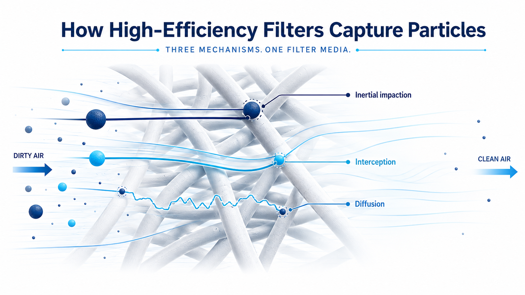
HEPA and ULPA filters do not operate only by screening particles through openings smaller than the particles themselves. Instead, particles are captured as they travel through a complex network of fibres.
Inertial impaction
Larger particles cannot follow rapid changes in the airflow path and collide directly with filter fibres.
Interception
Particles following the airflow pass close enough to a fibre to make contact and become trapped.
Diffusion
Ultrafine particles move irregularly through Brownian motion, increasing the probability of contact with a fibre.
Depending on the filter media, electrostatic effects may also contribute to particle capture. Overall performance is influenced by particle size, fibre diameter, media structure, airflow velocity and pressure drop.
What Is FERENA Nanofiber Filtration?
HEPA and ULPA describe established categories of high-efficiency filtration. FERENA, by comparison, is a nanofiber filtration technology developed for use in KOACH cleanroom systems.
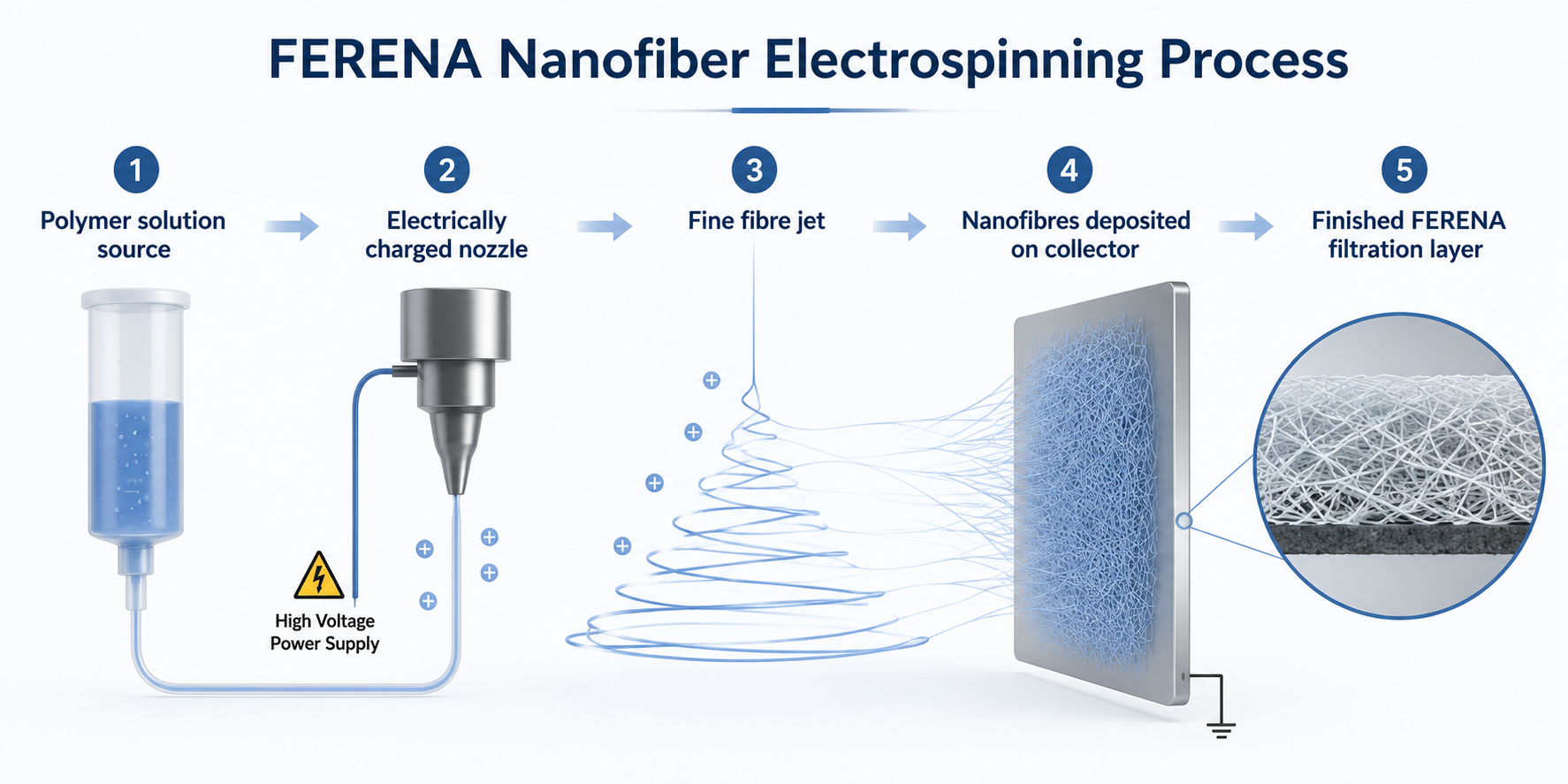
FERENA filter technology is manufactured using an electrospinning method. This process creates an interconnected network of extremely fine fibres. The fine nanofiber structure provides a large particle-capture surface while maintaining pathways through which air can move.
FERENA provides 99.9998% removal of particles measuring 0.15 µm and is designed to offer lower air resistance than conventional commercial ULPA filtration.
HEPA vs ULPA vs FERENA: Key Differences
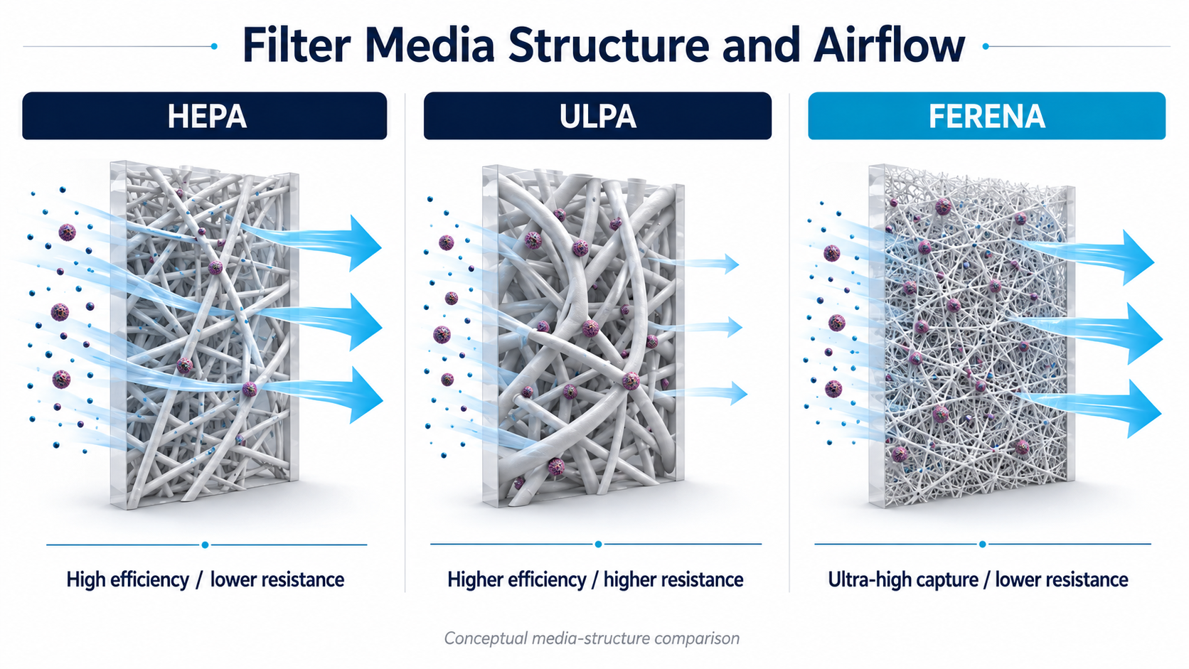
| Comparison point | HEPA | Conventional ULPA | FERENA |
|---|---|---|---|
| Technology type | Established high-efficiency filter category | Established ultra-high-efficiency filter category | anofiber filtration technology |
| Stated filtration performance | At least 99.97% at 0.3 µm | Commonly stated as 99.999% at approximately 0.12 µm | 99.9998% removal at 0.15 µm |
| Media structure | Fine fibrous mechanical filter media | More restrictive high-efficiency filter media | Electrospun nanofiber network |
| Airflow resistance | Generally lower than conventional ULPA | Generally higher | Lower than commercial ULPA |
| Primary strength | Practical balance of filtration and airflow | Very high removal efficiency for ultra-clean applications | Ultra-high particle removal with lower air resistance |
| Typical positioning | General controlled environments and cleanroom HVAC | Highly contamination-sensitive environments | KOACH localised clean-zone technology |
Why Airflow Resistance Matters
Filtration efficiency is only one part of filter performance. Air must also pass through the filter media at the volume and velocity required by the cleanroom or clean-zone design.
The resistance created as air moves through a filter is commonly expressed as pressure drop. More restrictive media may require greater fan capacity to maintain the required airflow. This can increase the load on the airflow system and make it more difficult to maintain stable air velocity.
Conventional ULPA filtration often achieves very high particle capture using relatively restrictive media. FERENA uses a fine electrospun nanofiber network designed to provide ultra-high particle capture while maintaining lower air resistance.
Higher efficiency alone does not define the best filter
The practical objective is to achieve the required cleanliness level while maintaining controlled airflow, manageable pressure drop and reliable operation around the process.
FERENA as Part of a Complete Cleanroom System
A filter alone does not determine the ISO classification of a cleanroom or clean zone. Air cleanliness is determined by the concentration of airborne particles measured within the controlled environment.
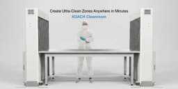
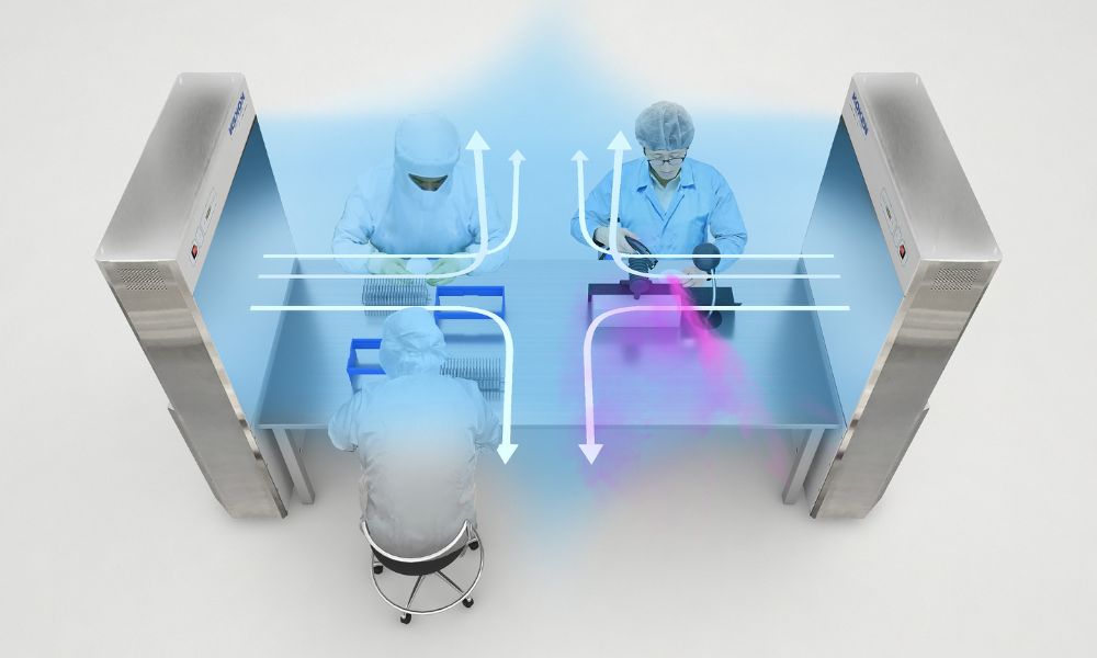
In KOACH systems, FERENA filtration operates as part of a broader contamination-control approach that includes filtered airflow and coherent unidirectional laminar side airflow. This integrated system is designed to create a localised ultra-clean area around the process, equipment or sample.
By combining nanofiber filtration with controlled airflow, KOACH provides an open-system approach for creating clean environments up to ISO Class 1 conditions without requiring a conventional full-room cleanroom around every application.
How to Select the Appropriate Filtration Technology
The highest filtration-efficiency figure is not automatically the best choice for every controlled environment. Selection should be based on the process, the particles of concern and the performance required from the complete airflow system.
Explore HORIBA ISO Class 1 Cleanroom Solutions
Learn how KOACH combines FERENA nanofiber filtration with coherent unidirectional laminar side airflow to create a localised ultra-clean working environment.
View ISO Class 1 Cleanroom Solutions